AN-113: Transformer Laminations; History & Theory Applied to Audio Transformers
By: David Geren
People interested in how high performance audio transformers work call their engineering “black magic.” In fact, it is the confluence of science, application of the science to engineering, and the experience of the engineers designing and manufacturing the completed product. Various disciplines are involved. Here, we will set out only a few of the scientific and engineering factors relating to the “soft” magnetic core laminations needed for successful audio transformers employing laminations. Simple algebraic formulas will be used. Attention to what the formulas actually “say” will give greater insight into the topic.
Brief History Of the Discovery of Principles of Magnetic Induction
In 1820, Hans Christian Orsted noticed that the needle of a compass next to a wire carrying an electric current was deflected perpendicular to the wire. He reported that the magnetic field was perpendicular to the conducting wire and that it changed direction if the current flow was reversed. This directionality can be remembered by one version of the “right hand rule” where the fingers of the right hand are curled around and the thumb is pointed out. If the direction of current flow (I) is in the direction of the thumb, the magnetic field (B) follows the direction of the curled fingers.
On August 29, 1831 English scientist Michael Faraday described in his notebook the induction of an electromagnetic force between two coils of wire wrapped on a toroidal iron ring. When he pulsed one coil with a direct electrical current from his battery pile, a pulse of current was induced in the other coil. He called it a “wave of electricity.” He also noted that, when he changed the ratio of turns between the two coils, that there was a proportionate change in the induced amplitude of the pulse on the secondary. He then determined that he could induce an electric current in a coil of wire by changing the magnetic field across a coil of wire. This knowledge allowed him to make an instrument that generated electricity when cranked by hand, being the first dynamo generating direct current.
Figure 1
Faraday Direct Current Dynamo
In 1845, Franz Ernst Neumann mathematically described the induction of electric currents.
Between 1861 and 1862, James Clerk Maxwell used Faraday’s findings and used differential calculus to describe what was happening in time-varying electromagnetic induction. Those equations were later refined by Heaviside to describe motional emf (electro-mechanical force). Heaviside’s equations became known as Maxwell’s equations.
The Michelson-Morley experiment was conducted in 1887 to see if it was possible to use light beams to measure the motion of the Earth rotationally as well as around the sun. It compared the speed of light in perpendicular directions looking for any difference, using a interferometric setup illuminated by a coherent light beam. No difference was measured in spite of the high sensitivity of the experiment. Their conclusion was that the speed of light (“c”) is a constant no matter the speed of the measuring device.
In free space, electrons move at the speed of light. In solid conductors, the speed is reduced. The “free electron model” establishes the “Fermi velocity” named after 20th century Italian-American physicist Enrico Fermi. Absent electrical fields, the Fermi velocity in a metallic conductor is approximately 1×108 cm/s, or about 1% the speed of light. Work in the 19th century on what they thought was electron velocity in long cable work established that propagation along a conductor is dominated by distributed inductance and capacitance. These later factors, not the Fermi velocity, are the engineering considerations in the design of wide frequency response transformers and other electro-magnetic devices employing metallic conductors.
Side Note about the interaction of discoveries in physics: Albert Einstein apparently attributed his initial groundwork and the subsequent discovery of the laws of Special Relativity to the work of Michael Faraday from 1834. Einstein’s foundational insight into Special Relativity was inspired in part by the fact that it did not matter whether Faraday’s magnet was stationary and the coil moved, or if the coil was stationary and the magnet moved. It is the same whether the observer is moving or the measured object is moving. As Faraday deduced, the induced current was the same. Einstein took into account that the speed of light was constant no matter the speed of the observer, as had been established by the Michelson and Morley experiment. Relativity dictates that the speed of light will be the same no matter how fast the observer – or the observed system – is moving. This has a profound effect on measurements and the nature of space and time.
Brief History of the Invention and Improvements of Transformer Core Materials
For electromagnetic devices, cores are divided into two categories, “soft” and “hard” materials. Soft materials in this context refers to those in which a oscillating magnetic field (B) can be readily induced without permanently magnetizing the core. They are used for transformers and inductors. “Hard” magnetic core materials, once magnetized, hold onto the induced field and resist demagnetization. They are used for permanent magnets.
Silicon Steel Laminations:
Initially, transformer and motor cores were made with iron (atomic symbol Fe). Early on, it was discovered that those cores were subject to inefficiencies caused by eddy currents induced in the core by alternating current. Eddy current losses could be mitigated by using thin layers of sheet iron.
After a certain point, the iron sheet out of which the cores were made could not be practically made any thinner.
In 1882, British metallurgist and steel works proprietor Sir Robert Hadfield discovered manganese steel which was one of the earliest successful steel alloys. He included in related patents the addition of Silicon (Si) to the iron alloy which gave it better mechanical properties. He later discovered that Silicon steel alloy gave it superior electrical characteristics.
The addition of Silicon increases the permeability of the alloy. It was later determined by Bozorth in 1951 that permeability increased because the alloy now had low magneto-crystalline anisotropy, i.e. the magnetic characteristics were similar independent of direction of application of coercive force H (the energizing force) which induces the magnetic field (B) in the material. He also showed that the magnetostrictive coefficient (the change in physical size of the material as a function of B) was improved, reducing mechanical vibration of the core. However, magnetostriction is not eliminated.
Silicon also increases the electrical resistivity of the alloy, typically by a factor of 5. This resistance reduces eddy current magnitude. Think of this as a resistor in series with a battery. Silicon content could be increased up to 6%, but mostly kept to 4% or less. Treating the surface with a resistive material is important because it limits electrical conduction between layers, thereby not allowing more eddy current losses.
Iron atoms form small crystals with random orientation. Each crystal has a preferred direction of easy magnetization. Because these crystals have a random orientation, the iron has low magneto-crystalline anisotropy – the force to magnetize a sample is equal in any direction that the electromagnetic force (H) is applied.
Figure 2
Atomic force microscope (AFM)
view of atoms of iron (Fe) and
Silicon (Si) in alloy
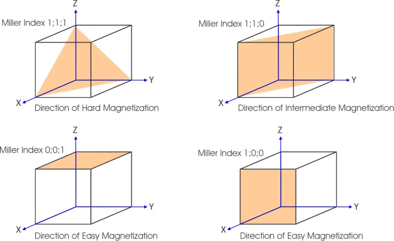
Transformer laminations typically are processed to intentionally consist of crystals with a predominately uniform orientation. The purpose is to promote high “permeability” which is affected by the ease of inducing a magnetic field. This orientation is characterized by Miller Index planes.
Figure 3
Iron (Fe) cubic crystal hardness of magnetization.
Miller Index planes. Note the planes requiring more magnetization energy (H) are not on the crystal faces.
This type of lamination steel is called “Non-Oriented electrical steel”. (“NO” electrical steel) It is commonly used in motors and generators.
The manufacture of silicon electrical steel begins with the starting materials (iron ore and scrap steel) being melted in an electric arc furnace. Silicon (plus other elements in trace amounts) is added to the melt.
“NO” steel billets are hot rolled into sheets. Next, they are annealed resulting in randomly oriented crystal grains. This process is repeated until the final thickness is achieved.
Fig 4
Non Grain Oriented
metalogrpah showing
crystal structures
Bulk metals and their alloys are comprised of metallic crystals. Annealing increases the size of crystals, randomizes their orientation which changes the magnetic properties, and makes it more ductile.
Grain-oriented silicon electrical (GO) steel was described in 1935 and then patented by Norman Goss. (US Patent 1965559) He took hot-rolled annealed electrical steel, cold-rolled it to make it thinner, and annealed it, thereby making it ready to cold roll again. This was repeated until the desired final thickness was reached. Superior magnetic properties were obtained because the crystals tended to align in the direction of cold rolling. It was found that silicon content could be increased up to 3.2%, after which the alloy became too brittle to readily work. Because of this process, the electrical resistance is greater in the direction of rolling. Electrical resistance plays a factor in eddy current formation, infra.
The GO process results in elongation of the contained metallic crystals in the direction of rolling. Miller Index planes (Fig 3) such as 0;0;1 and 1;0;0 are preferentially aligned in the direction of rolling, increasing the permeability in that direction. The overall permeability of the stamped out lamination is superior to NO electrical steel because crystalline orientation is less random and significantly more in one direction.
According to this formula, inductance of a coil arranged around a core changes in direct proportion to permeability. If the permeability (μ) doubles, the inductance doubles.
Figure 5
Magnetic domains and
domain walls in Grain
Oriented (GO) electric steel
Because of these factors (among others which will be discussed below) GO steel is the preferred material for high quality audio transformers that employ steel laminations. The cost is more than NOES because of the additional processing steps.
In 1824, the German chemist Johann Wolfgang Döbereiner conducted experiments that contributed to the understanding of nickel’s magnetic properties. However, it was not until later in the 19th century that more detailed studies were conducted, particularly as the field of magnetism began to develop with the work of scientists like James Clerk Maxwell and others. Nickel’s ferromagnetic properties were more thoroughly characterized in studies of magnetic materials next conducted in the late 1800s.
In 1914, Gustav Elmen at Bell Laboratories invented “Permalloy” which was an alloy of approximately 80% nickel (Ni) and 20% iron (Fe). It had very high magnetic permeability which made it superior in some applications for electrical and electronic transformer cores. Permalloy also was excellent at shielding devices from interference from external magnetic fields.
Permalloy is not very ductile. Other alloys were developed to soften it and make it more readily shaped by adding molybdenum (Mo) and a trace of silicon (Si). Those alloys have been called by various trade names and commonly used terms such as MuMetal, Mumetall, mu-metal, μ-metal, and the registered trade name “HYMU-80″.
BH Curves
BH curves can be somewhat mysterious if you dive right into the physics and engineering concepts behind it. The curves are important in evaluating the composition and processing of magnetic core materials. Signal level audio transformers mostly rely on μ-metal alloys. The objectives in the creation and final processing of those alloys will become more understandable at the end of this section, starting at Figure 17.
Take a few minutes to analyze the following formulas. They explain the interaction of “H” and “B”. This is simple arithmetic. For purposes of this discussion, we do not need calculus (Maxwell and Faraday Equations) to explain the dynamics over time.
“H” is the magnetizing force that creates magnetic flux (“B”). If H is constant B also is constant. Consider a permanent magnet that is not moving placed next to a coil of wire. Electrons do not flow because the magnetic field can not push the electrons around the coil and then into an external load. It takes energy to move electrons. A stationary magnetic field does not induce any energy flow into the system.
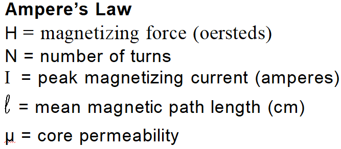
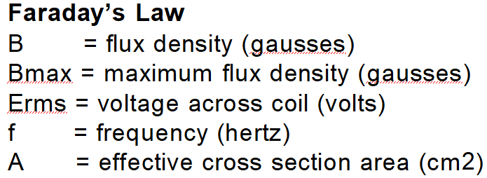
In electromagnets and transformers, the magnetizing force (H) is induced by the electric current flowing in a coil surrounding the magnetic core material. This induces a magnetic field (B) in the core. Those relationships are given in the following three formulas.

The magnetization cycle starts here:
Eddy currents
Eddy currents are loops of electric current induced within conductors by a changing magnetic field, and they can lead to energy losses in transformers. Being metallic, transformer laminations do conduct electricity and thus are subject to eddy current losses. To minimize eddy currents, transformer cores typically are laminated.
The eddy current loss (Pe ) in a laminated core can be calculated using the following formula:
Where:
Pe = Eddy current loss (in watts)
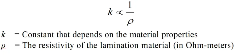
k = Constant that depends on the material properties (typically determined experimentally)
B = Maximum magnetic flux density (in teslas)
f = Frequency of the magnetic field (in hertz)
t = Thickness of the lamination (in meters)
V = Volume of the core (in cubic meters)
As mentioned supra, electrical steel employs silicon (Si) atoms in the alloy to increase the electrical resistivity of the material. Nickel alloys inherently display high resistivity (as well as higher permeability). They typically have molybdenum (Mo) and a trace of silicon (Si) which further increase resistivity. Power loss solely due to resistivity can be understood with Ohm’s Law:
Other factors are involved in determining k, but it can be summarized as follows:
Eddy current losses are minimized by using thin laminations with high resistivity. Grain oriented electrical steel, being rolled, has higher resistivity in the direction that it was rolled. (It is sometimes called “GOS” or “GOSS” for grain oriented steel.) High nickel laminations have high resistivity in both the x and y axis. Using thin laminations also reduces eddy current. All laminations have a resistive coating, which keeps them from shorting out.
Audio signal transformers operate in the sub-milliwatt range. However, eddy current losses can become important when they are subjected to high amplitude impulses because they can generate a high enough flux density (B) inducing eddy current loss. Hence, in high performance audio transformers, high resistivity is an important consideration. Eddy currents contribute to distortion. This loss is in proportion to the square of the frequency.
Considerations in Lamination Performance
The distortion characteristics of the laminations chosen in the design of a audio transformer is a major factor in the engineering process. Non-linearities in the BH response result in harmonic distortion. The harmonic distortion level and distribution over frequency is governed by the signal level and the flux (B) in the transformer core.
These harmonics may be desirable in some applications, resulting in the elusive “transformer sound.” Understanding these BH curves and the operating level range helps for the design of a successful audio transformer. It must be kept in mind that each batch of laminations will have slightly different properties but should fall within a predetermined bracket.
Input Transformer Laminations
The audio input transformer category includes microphone and line transformers. They operate at signal levels work best with alloys having 80% nickel content because of these considerations:
a) Non-linearity at the low end of the BH curve will contribute unwelcome harmonic distortion. Normal listening level mainly occupies the lower portion of the curve.
b) 50%Ni alloys do not have a linear BH curve response at low levels. (Fig 20) This is indicative of higher Br (neutralizing current, i.e. energy).
c) 80%Ni alloys are linear down to significantly lower levels than 50% alloys. (Fig 21)
d) 50%Ni alloys reach saturation faster than 80% alloys. (Fig 18)
e) 80%Ni alloys can be processed to produce better operating levels and linear BH response over a much wider range than 50% alloys. (Figures 18&19)
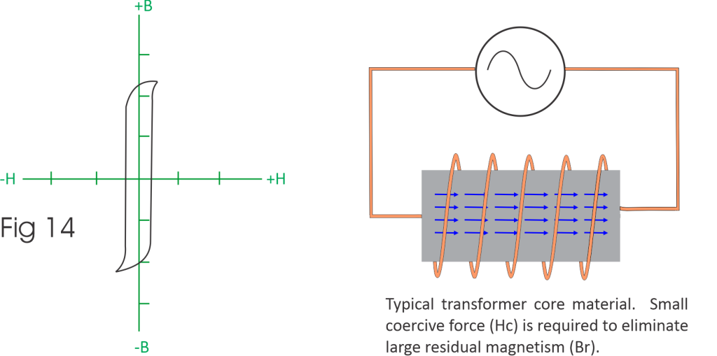
Steel laminations do not work well with input transformers because the excitation current requirement is too high. Br is governed by the energy (H) needed to pull the magnetization of the core past zero and reverse direction. (Figures 8&11) These formulas, which we first saw above, help understand this concept when considering the portion of the BH curve occupied by Br and the power needed to overcome it. Keep in mind that he area inside the curve determines the power loss.
This effect is visible in the BH curve for steel laminations in Figure 17. Steel laminations do have a place in many audio transformer applications, but not input transformers which depend upon high permeability core material.
Output & Interstage Transformers
Audio line output and interstage transformers can employ many different lamination types. This is because they predominately operate in a much higher signal regime than input transformers.
High-nickel laminations offer the lowest harmonic distortion. However, it is far more costly than steel. Br is quite low, which can be seen comparing Figures 20 & 21.
Some output transformers use the low nickel (+/-50%Ni) alloy. It is less expensive than high-nickel. he BH curve is much steeper. (Figure 18) Because of the steep BH curve, it has a distinctive harmonic structure compared to either high-nickel or steel.
Steel has an even more pronounced harmonic structure. Grain oriented steel is preferred for audio applications. Figure 17 BH curve illustrates that it has nonlinear response to where H is +/-50 Oersteds and smooths out on a curve as the field continues to approach the saturation point. This is one of the significant contributors to “steel transformer sound”.
Cobalt laminations are infrequently used or included in the stack. They contribute another set of nonlinear BH curves.
Nickel Lamination Treatment
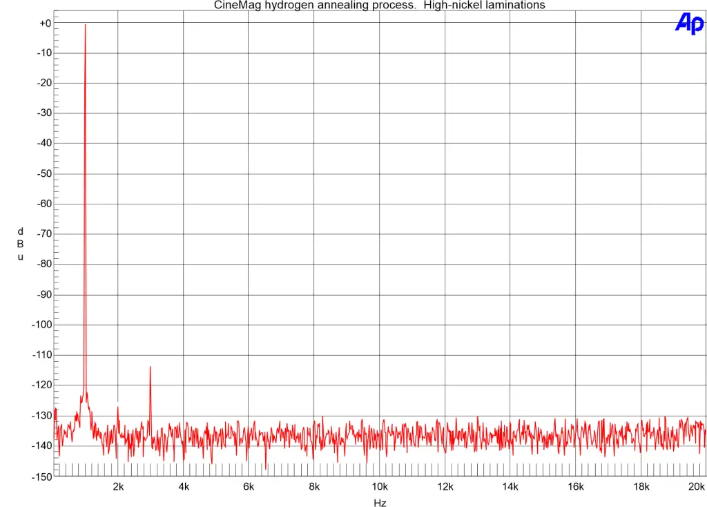
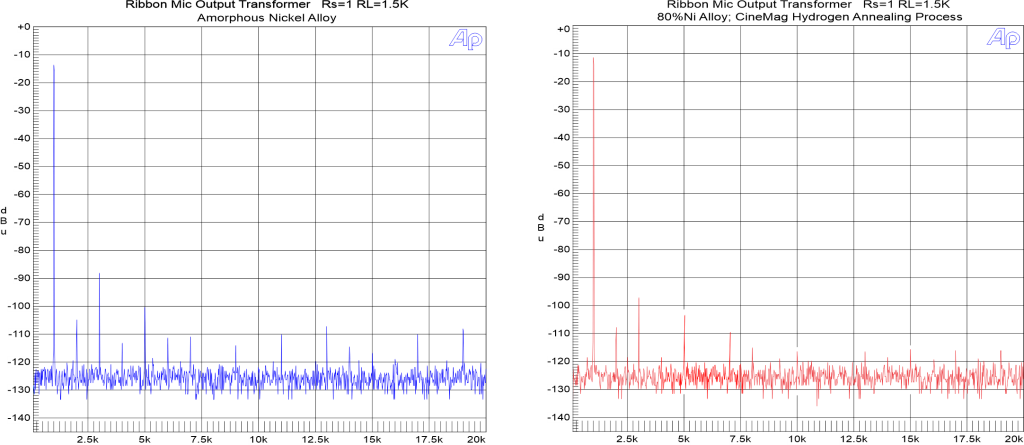
High nickel laminations are annealed in a pure hydrogen (H2) atmosphere. No other atoms are allowed into the hydrogen furnace. This process is configured to linearize the BH curve, allowing for low harmonic distortion. At high temperature, hydrogen will partially penetrate into the alloy. It does not form strong bonds with the alloy constituents and is released during the cooling process. Hydrogen annealing of nickel alloys encourages formation of large crystals. This results in less total contact area between the metallic crystals. The reduced contact area corresponds to less energy lost to pass the magnetic field through the alloy. Hydrogen annealing promotes large crystal formation without creating a specific crystal geometry orientation. Optionally, a magnetic field can be introduced across the laminations during annealing to encourage grain orientation. Not all hydrogen annealing processes are the same. Figures 22 and 23 illustrate the difference between very good annealing and CineMag’s proprietary multi-step process. The stock for each test came from the same μ-metal mill.Figure 22
Standard hydrogen
annealing of 80%Ni
μ-metal laminations
Figure 23
CineMag hydrogen
annealing of 80%Ni
μ-metal laminations
Amorphous Nickel
Amorphous metal has been employed in a few audio transformer designs that have been released into commercial production. This class of material has also been called “metallic glass”, “glassy metal”, or “bulk metallic glass”.
The atomic structure of all amorphous metals is disordered, being non-crystalline. This distinguishes them from almost all other solid metallic materials because those materials have a crystalline structure. The objective of cold rolled electrical steel and the heat treatment processes of transformer laminations is to take advantage of crystal structures. Standard nickel laminations are hydrogen annealed at very high temperature for a long time, after which the batch is slowly reduced to room temperature. This encourages the growth of large metallic crystals.
Amorphous transformer materials are typically formed in thin strips. The alloy is first brought to a high temperature and then cooled extremely rapidly. The rate of cooling can be in the millions of degrees C per second. This is too fast to allow for the nucleation and formation of crystals.
Amorphous transformer cores work because they rely on their glassy atomic structure. If this is disrupted by inappropriate mechanical stress, their magnetic characteristics can be altered. Sometimes thin strips are wound to create a solid core. Some cores are sawed to allow coil bobbins to be slipped into place. These split cores are typically held together by a steel band. Some companies thread long strips through the coils repeatedly to build up the core. Care must be taken not to strain the core material lest it induces greater harmonic distortion.
While amorphous materials start out with excellent manufacturer specifications, they do have harmonic distortion issues. The amorphous alloy used for this test was continuous strip material:
Figure 24
References
[1] Arnold Rolled Products. 4mil Grain Oriented Silicon Steel Hysteresis Curve at 400Hz
[2} Modeling Dynamic Hysteresis Curves in Amorphous Magnetic Ribbons. Krzysztof Chwastek; Mariusz Najgebauer; etc. Appl. Sci. 2023, 13, 9134. https://doi.org/10.3390/app13169134 Published 2023
[3] N.P. Goss U.S. Patent 1,965,559
[4] Transformer and Inductor Design Handbook. Colonel Wm. T. McLyman. Third Edition. New York, United States: Marcel Dekker Inc., 2004.
[5] Fe-Si Electrical Steels for High-Efficiency Electric Machines; A Study of Ductility and Magnetic Properties. Navid Farzam Mehr, Clausthal University of Technology. 24 March 2025
4487 Ish Drive, Simi Valley, CA 93063
(818) 993-4644
cinemag@cinemag.com