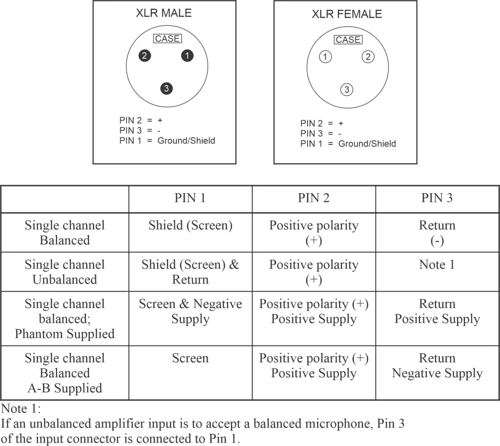
3-Pin AES XLR Connector Pinout
Given that pin assignments for XLR audio connectors had been inconsistent over the years, in 1992 the Audio Engineering Society published standards documenting the configurations most commonly used in the industry (Application of Connectors, Part 1. XLR-type Polarity and Gender. AES14-1992). This application note summarizes the widely adopted pin assignments for 3-pin AES XLR connectors and explains why proper handling of the two distinct grounding systems — earth/chassis ground and signal ground — is essential for achieving hum-free performance in professional audio systems.
Recommended AES XLR Pin Assignments for Compatibility
The chart below lists what the pin assignments are for to be compatibile with virtually all audio equipment in use today. The schematic shows how to hook up the connectors and how to wire the cables for maximum benefit of grounding and signal quality.
IMPORTANT: There are two distinct grounding systems in any system: (i) earth/chassis ground; and (ii) signal ground. Failure to properly deal with them can allow for ground loops which will introduce hum into the signal. This is why a 3-pin connector actually has four (4) connections.